KegData Installation
The installation of the KegData system is simple. Below are the steps and information to install a system and the tools needed.
Below is a typical installation of a 6 keg system in a restaurant. You may also follow the step by step instructions below.
Tools Required
- One large crescent wench
- One power drill with 1/2" metal bit
- One pair of diagonal pliers
- Two pair of vice-grip pliers (optional)
- Phillips Screwdriver, or bit for drill
System Layout
There are two basic types of setups as far as where the keg(s) are located, a walk-in cooler or a refrigerator, and how many you have. We will deal with both types of installations.
Refrigerator
If you are installing this system in a refrigerator it is often not necessary to put the Hub Controller into the refrigerator, but rather next to it. This all depends on the insulation characteristics of the refrigerator and if the signal from the coupler can reach the hub through the refrigerator wall. You can power up the system with the hub outside of the refrigerator to see if an exterior location will work. If not the installation is very similar to the setup for a walk-in.
Walk-in Installation
There are several things to consider before you start. How many couplers will you be installing, antenna location and providing power to the unit. We will be looking at a normal 4 keg installation. If you can get power from within the walk-in cooler that is best.The first photo below FIG 1 is the simple installation of 4 kegs in a typical walk-in. The power for this system comes from a hole under the Hub Controller "HUB". You will see the purple wire that runs the power to the Power Distribution Board "PDB". From here the power goes to the kegs and back to the HUB. Also note that in most installations the beer line and CO2 lines are tied together with zip ties. When you install the KegData system you will attach the power wire to the CO2 line with zip ties.
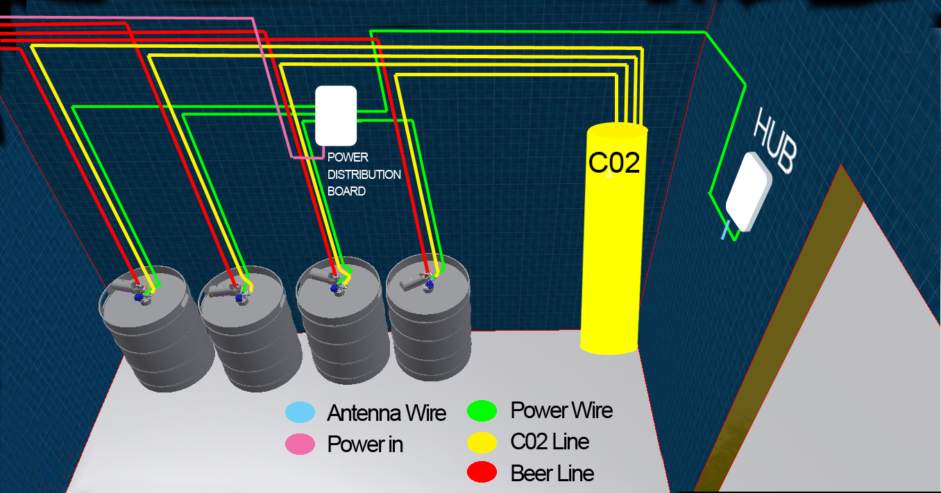
Fig 1
Installation of 4 Kegs in typical walk-in
Now in figure 2 below you will see that the power wire will go in and the antenna wire out. If you do not want to drill a hole in your walk-in you can see FIG 3 below.
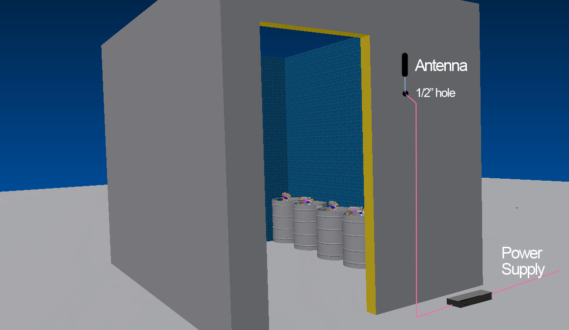
Fig 2
Power Wire and Antenna Wire
In the photo below the power wire goes in and the antenna wire comes out through the hole already in the ceiling where the beer lines go out.
The HUB and the PDB are next to each other in the walk in. The antenna can lay on top of the roof or attached to a wall of structure to get the best reception.
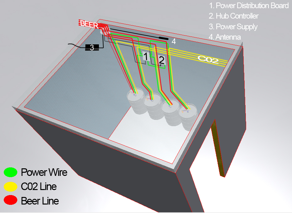
Fig 3
Power Wire and Antenna Wire
The Power Distribution System
There are three items that can be used to provide power to the HUB and the Couplers. There is the 3 way splitter, the 8 port power distribution board "PDB" and the 24 port PDB. Depending on the number of kegs, you can chose the appropriate part or combination of parts to keep your wiring organized. All three of the power distribution items can be "daisy chained". In other words if you had 4 kegs on one wall and 8 on the other, you would use two 8 port PDBs as shown in FIG 4 below. You would also need to order the power jumper wire shown in yellow.
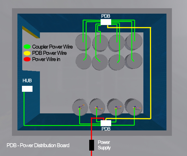
Fig 4
Two 8-port PDBs
Now you should know what you need as far as the power distribution system is concerned. Remember that the green power wires to each of the couplers will need to be zip tied to the CO2 lines. You can see an installation below in FIG 5, this makes for a nice clean installation.
You will need to estimate the length of the wires shown in green, FIG 4. The standards are 12' and 18' lengths. There is a 3' wire to go from the PDB to the HUB. If you want a longer wire you will need to select the proper one for your application.
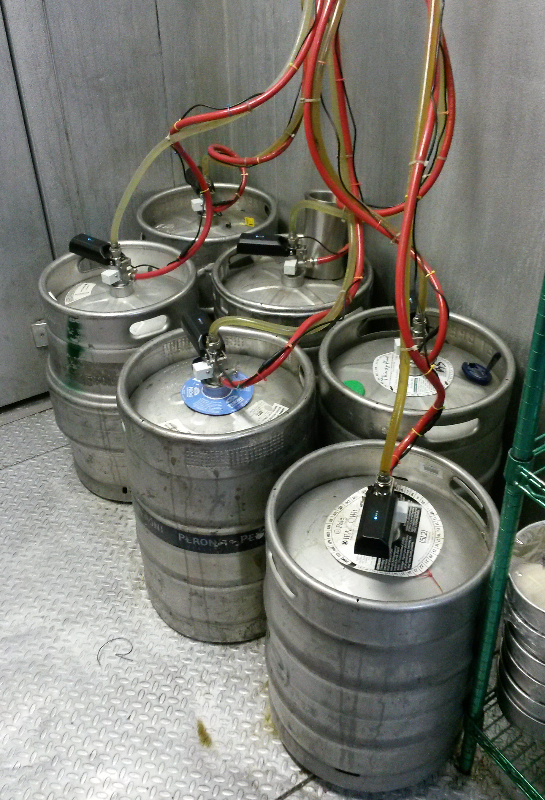
Fig 5
Installation at a restaurant
Figure 5 above shows an installation at a restaurant. You can see how clean the installation is and how the wires are attached to the CO2 lines.
Return to topPUTTING IN THE SYSTEM
We have also included an installation video to help you better understand the installation.
- Step 1
The first step will be to shut off the CO2.
You can also use the two needle nose vice grips (optional tools) to squeeze off the CO2 line and beer line.
- Step 2
Uncoupler the keg and take the old keg coupler off of the keg.
- Step 3
Remove the beer line and CO2 line from the old coupler and set it to the side. In your kit you will have a new CO2 check valve and a washer for the top beer line out.
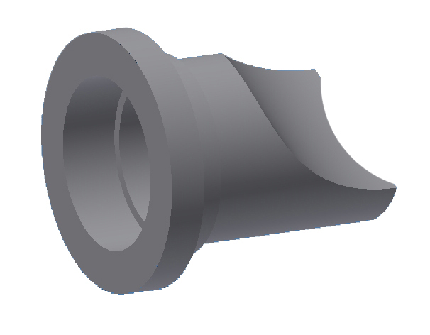
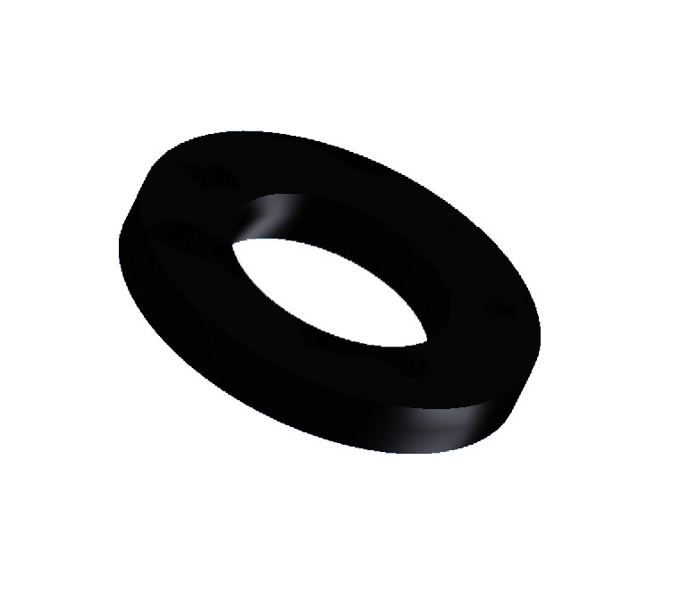
DO NOT FORGET TO PUT THESE IN!!
You can also use the old ones if they are in good condition - Step 4
Reattach up the beer line out to the top of the coupler and the CO2 line in. Make sure the washer seats properly. Repeat this until all couplers are replaced.
- Step 5
Put the new KegData couplers back on the kegs and push the handle(s) down to retap the kegs. You are now done with the coupler section.
- Step 6
To mount the Hub Controller select the spot to put your HUB from the guidance above. Drill two holes in the wall, 1/16" in diameter and 3" apart, one directly below the other.
Put in the two screws provided leaving them sticking out about 1/8". You can adjust this distance after you test fit the HUB.
Mount the hub controller to the wall by sliding down over the two screws.
- Step 7
Now we need to mount your PDB. It needs to be within 3 feet of the HUB if you want to use the factory 3' wire.
If you are using the 3 way splitter there is no mounting for this item.
If you are using the 8 PDB just mount with the two screws provided through the tabs diagonally. The other holes are provided in case the board is damaged and a tab is broken off.
On the 24 port boards, drill two holes in the wall, 1/16" in diameter and 6" apart, one directly below the other. Put in the two screws provided leaving them sticking out about 1/8".
You can adjust this distance after you test fit the 24 port PDB.
- Step 8
If you are using more that one power distribution device you will now need to run a power wire between the two or more devices. These are optional, be sure you have ordered these.
These power wires have a bigger end than the wires that go to the couplers so they are not interchangeable.
- Step 9
Now run the wires from the couplers to the PDBs or splitters, use the straight end at the coupler.
Use the zip ties to attach the power with to the CO2 lines. Bunch extra cable with a zip tie.
- Step 10
If you have not done so yet, run the power wire form the PDB or splitter to the HUB.
- Step 11
You should have already decided where you are bringing in the power, from a wall or through the roof, or from within the walk-in if it is available. Run the power wire to the PDB or splitter.
- Step 12
Now you will run the antenna out through a selected hole in the walk-in. This antenna must be able to reach a Wifi signal. If it cannot reach a signal it will not be able to send data.
Now attach the antenna to the HUB. This completes the installation of your system.
Setting up your Hub, WPS or Manual
- Step 1
Bringing your hub to a location that is physically convenient to your wireless access point makes this easier. Connect the antenna and power cable to the hub and allow it to boot.
- Step 2
Activate WPS on your wireless access point (typically a button). Please see notes below for more information.
- Step 3
Your wireless access point may have a soft button. Meaning that it is not a physical button, but rather a button you press when logged into its configuration page.
- Step 4
If you wait too long after pushing the wireless access point button before pushing the Kegdata button, your wireless access point will have timed out the WPS and you will need to start the process over.
- Step 5
If all else fails, you may need to read the directions for your wireless access point! Or revert to manual setup below. Please disconnect the power to the hub for 10 seconds to start over.
- NOTES ABOUT WPS:
- Note 1
There are 2 types, PIN and push button. Kegdata only works with push button. PIN mode WPS is not secure and we recommend you have it disabled on your access point.
- Note 2
Your wireless access point may come from the factory with WPS function disabled. If this is the case you would need to enable it by logging into its configuration pages.
- Note 3
Your wireless access point may have a soft button. Meaning that it is not a physical button, but rather a button you press when logged into its configuration page.
- Note 4
If you wait too long after pushing the wireless access point button before pushing the Kegdata button, your wireless access point will have timed out the WPS and you will need to start the process over.
- Note 5
If all else fails, you may need to read the directions for your wireless access point!
Manual Setup
- Step 1
For greatest convenience, we suggest you do this prior to physically installing the hub. Bring the hub to a location that is convenient to a laptop computer (with wifi) and within radio range of the wireless access point that you intend to use. Plug both the antenna and power cable into the unit and allow the unit to boot.
- Step 2
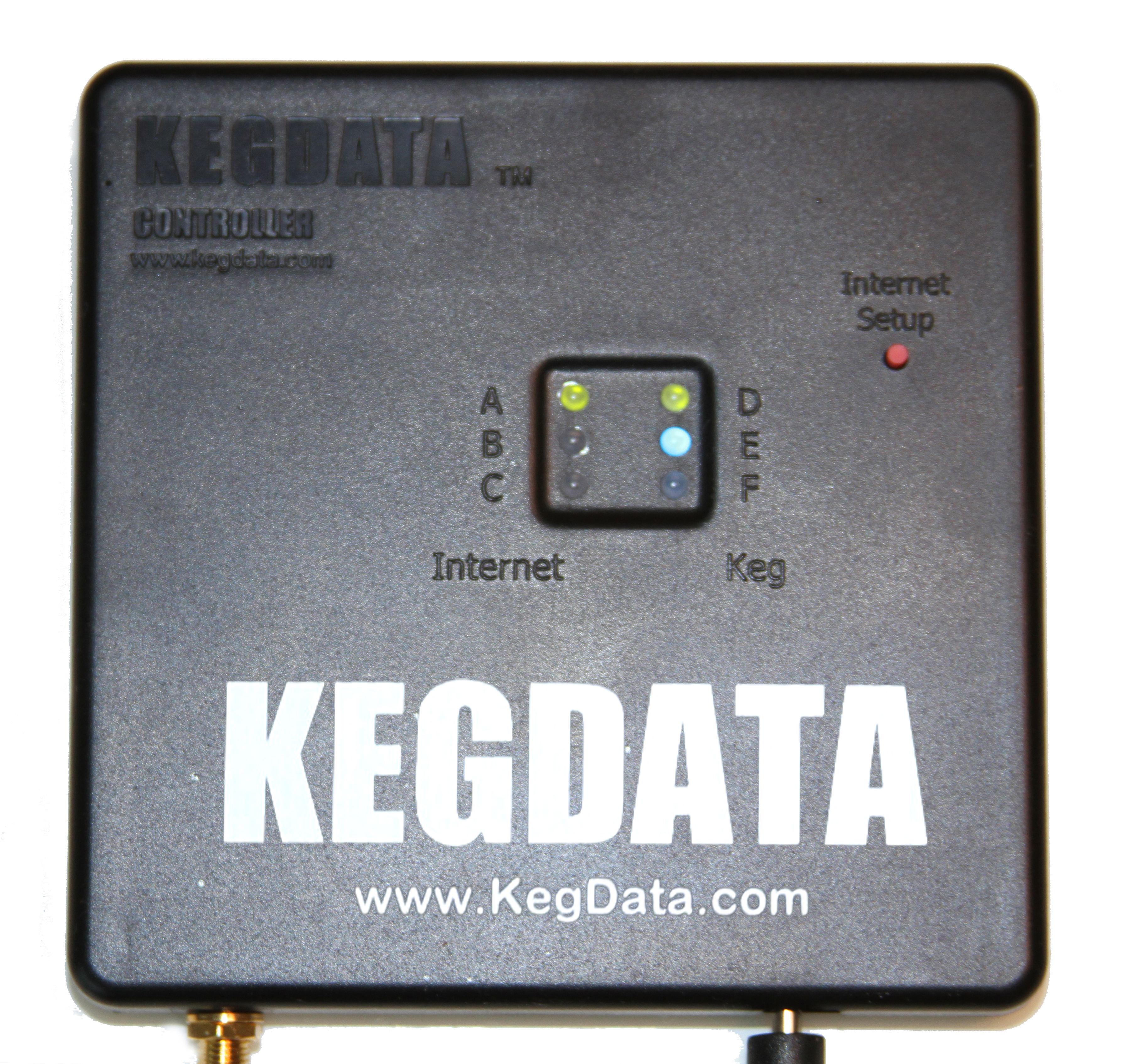
Hold down the "internet setup" button for 2 seconds then release. Look at the left bank of led's labelled "internet". Within 5 seconds you should see the red and green led's blinking back and forth (LED A and C). The amber (LED B) should be off. If you do not see this pattern within 5 to 10 seconds, repeat the button press.
- Step 3
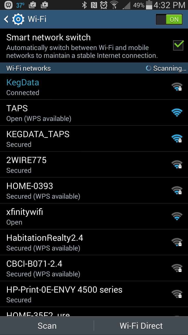
Moving to your laptop, open your wireless connections menu. Look for "KegData" as an available wireless network. Click on it and when prompted, enter the password: KegData123
- Step 4
Wait for the hub to show a solid green led (LED A), flickering amber led (LED B) and a red (LED C) that is not lit at all. This should take 5 to 10 seconds.
- Step 5
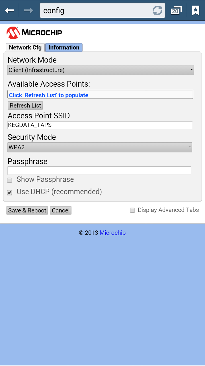
Open a web browser and enter the following in the url field at the top: config.html
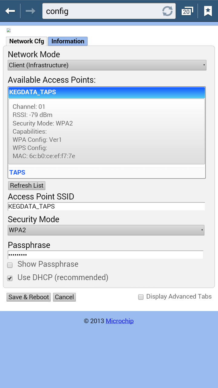
- Step 6
The configuration page should open. Click "refresh list" to have the hub search for available networks. When shown, click the network you intend to connect to. Scroll down further to the box labeled "passphrase" and enter your wireless network's password. Click "save and reboot".
- Step 7
Confirm connection. The green led (LED A) should be blinking once per second. The amber (LED B) may flicker. The red (LED C) should be off. If you still see the red led, then you will need to repeat the process. Perhaps the password was entered incorrectly.
- Step 8
Now it is time to set up your kegs on the KegData server. If you have not registered please do so first. The HUB controller will have to be registered to you so if you have not registered already you may have to contact KegData to tell them you HUB mac address located on the back of the HUB. When you login into the website you will immediately go to your "Dashboard". You will see your keg levels for all couplers that are transmitting. On each coupler there is a 6 character string, this identifies that coupler. If you have a lot of kegs it will save time to write down this identification number and the size of keg and contents for each of the couplers. Go to keg setup on your dashboard and set up each of your kegs. If you want to use the auto reorder portion, you will need to see if your distributor is registered. If not, ask them to register so they can see your keg levels.
Viewing the online videos on our website may make this process simpler. We suggest for greatest ease, that you connect your hub to the internet prior to physical installation. It is more convenient to do comfortably sitting at a desk as opposed to in a cold cooler balancing a computer on your keg! After connecting your hub to the internet, move the hub and antenna to the locations you plan to install them and confirm that it is still in radio range and able to connect. At this point, you can physically secure the system knowing that all is good.
There are two ways to connect your hub to the internet, manually or WPS. If your wireless access point has WPS, we suggest you try this method first.Using WPS Method:
Quick Directions that work for most wireless access points equipped with WPS.
Testing your System
NOTE: This system learns so your first pours might not register or might not register correctly until 5 or more pours.Your system should be working now. Every time you pour a beer you will see light B on your HUB blink yellow for a a brief moment and this will show up on your web page. You will also see the third green light, light C, on the coupler light up when your tap handle is opened, see the video below. Everything form here is pretty much on auto.
Return to top
